Lab 8
The purpose of this lab is to familiarize you with the UR3 robot and the tools we have for making it do useful and/or interesting things. Additionally, you will cause the end point of the robot arm to move in both a square and circle in a vertical plane and in a horizontal plane. The horizontal plane is the plane perpendicular to the Z-Axis and the vertical plane is the plane perpendicular to any line in the horizontal plane.
First, you will cause the end point of the arm to move in the largest possible horizontal circle. Then you will cause the endpoint of the arm to move in the largest possible horizontal square. Next, cause the end point of the arm to move in the largest possible vertical square. Finally, you will cause the end point of the arm to move through the largest possible vertical circle.
Note
You will first create a successful simulation of the desired arm movement in Gazebo. Only after getting this simulation approved by the lab staff will you implement it on the actual arm. This is a very important safety measure.
Running the simulation
Launch the Lab 8 simulation which opens both the Gazebo and RViz windows:
ros2 launch lab8 lab8.launch.py
Split the VSCode terminal either by pressing CTRL + SHIFT + 5 keys or by pressing this button
shown below.
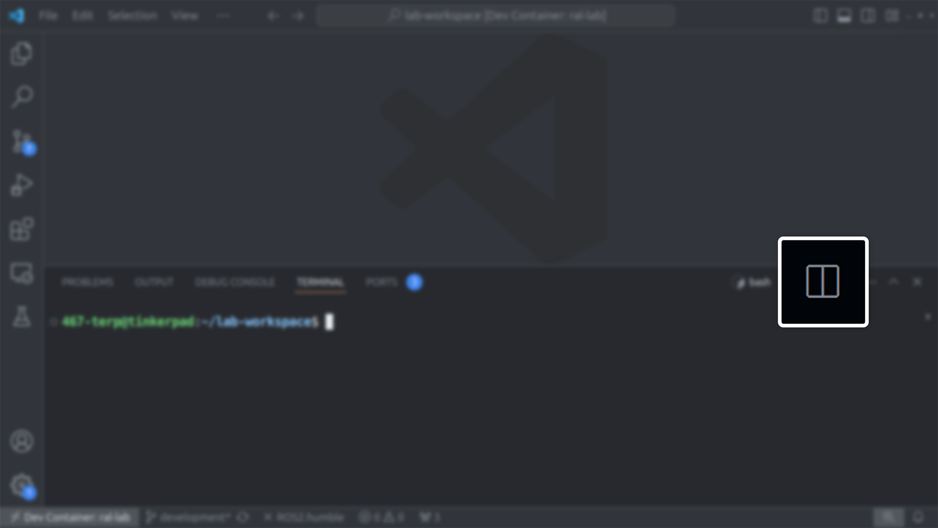
Split button for the VSCode terminal
In the new terminal, start the draw_shape node, which moves the robotic arm.
ros2 run lab8 draw_shape --ros-args -p use_sim_time:=true
This node demonstrates a few example motions with the robotic arm by default, which:
Orients the arm into position to draw a shape in the vertical plane using a joint-space goal.
Draws a triangle in the vertical plane by following a list of waypoints for the end-effector in Cartesian space.
Adjusts the end-effector to point upwards using a Cartesian-space goal.
Returns the arm to its initial position by specifying a predefined, named position (up in this case).
Writing the code
The source file for this lab exercise is located at lab8/src/lab8.cpp within the workspace’s
source directory. This is where you will write the code for this exercise.
Go through the code inside the examples.cpp file within the same folder to understand how the
motions observed in the simulation are implemented. You can also refer
this page for more detailed explanations of any section of
the code as needed.
Now, use the reference code to write your own implementations for the following functions in the
lab8.cpp source file:
UR3eMoveInterface::drawCircleXYUR3eMoveInterface::drawCircleYZUR3eMoveInterface::drawSquareXYUR3eMoveInterface::drawSquareYZ
Build the packages and source the workspace after writing the code.
cd $ROS_WS && colcon build && source install/setup.bash
Running the program to draw shapes
The command for running the draw_shape node takes three arguments to define the shape, plane,
and size. The node can be executed repeatedly with different argument combinations.
ros2 run lab8 draw_shape <shape> <plane> <size> <ros-args>
- <shape>
Options:
circle,square- <plane>
Options:
horizontal(XY Plane),vertical(YZ Plane)- <size>
Radius if
<shape>iscircleand side length if<shape>issquare- <ros-args>
Mainly for setting the
use_sim_timeparameter totruefor simulation. This isn’t needed for the real arm.- Example 1:
For drawing a circle in the horizontal plane with a radius of 0.25 meters in simulation.
ros2 run lab8 draw_shape circle horizontal 0.25 --ros-args -p use_sim_time:=true
- Example 2:
For drawing a square in the vertical plane with a side length of 0.2 meters on the real arm.
ros2 run lab8 draw_shape square vertical 0.2
Note
The program defaults to running the examples function if any of the <shape> or <plane>
arguments are missing or incorrect.
Leaving the <size> argument as blank will set the maximum size of 0.45 m radius for the circle
or \(\frac{0.45}{\sqrt{2}}\) m side length for square.
Controlling the real UR3e arm
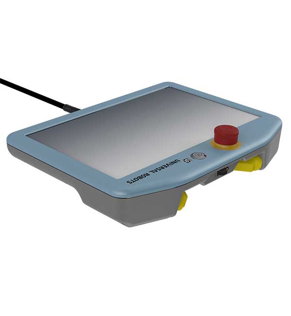
Start the robot by turning on the Teach Pendant. Open the Initialization
window by pressing the button at the bottom-left corner of the screen. In the Initialization window,
press ON and then START to release the brakes.
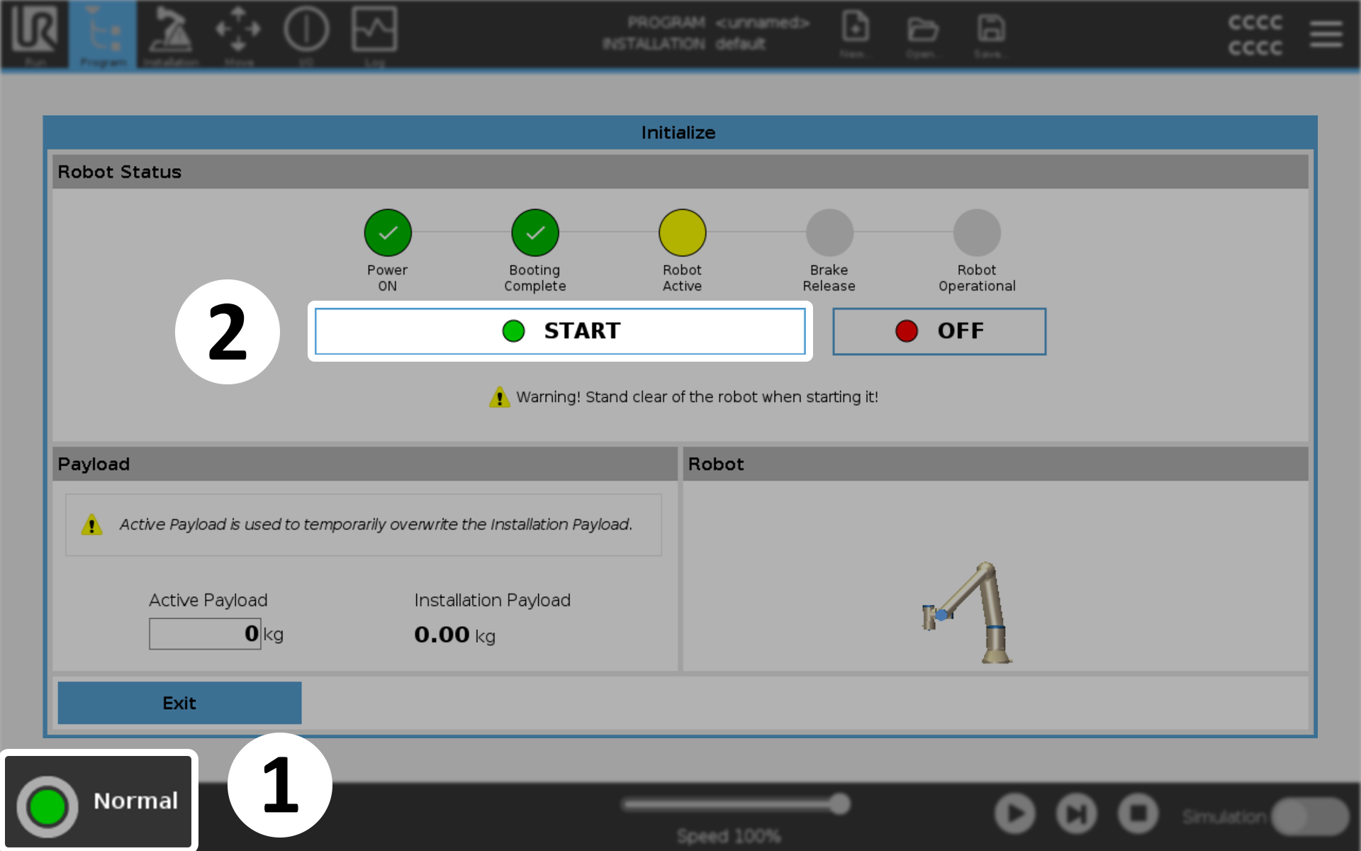
Initializing the arm
Then on the lab computer, launch Lab 8 with the sim argument set to false.
ros2 launch lab8 lab8.launch.py sim:=false
This starts the UR ROS Driver which communicates with the real arm instead of Gazebo simulation.
The arm shown in RViz sits in the upright position if the ROS driver successfully communicates with UR3e. This might take some time.
Then on the Teach Pendant, start the ur3e_ros program.
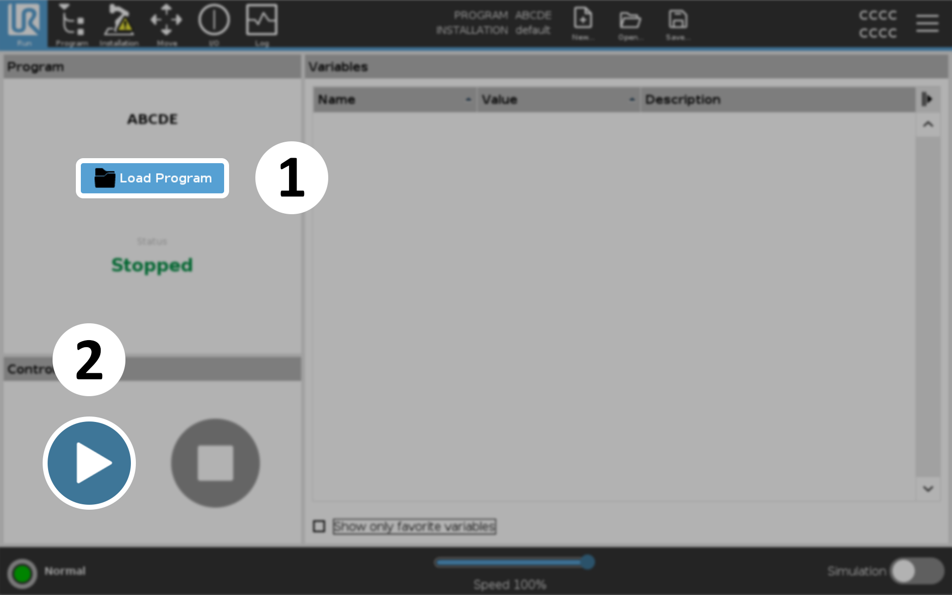
Starting the program to receive commands from lab computer
Signs that the connection successfully established:
The terminal from which you launched Lab 8 should print
Robot connected to reverse interface. Ready to receive control commands.Doing a
ros2 topic listshould print a lot of new topics.
Caution
If there are any warnings or errors in the output, stop immidiately and ask the TA or the lab manager.
Then in another terminal, run the draw_shape node to start drawing the shapes with the arm.
Refer back to this section for more.
ros2 run lab8 draw_shape <shape> <plane> <size>
If you enabled end-effector tracking, the plots and CSV files of the end-effector positions will be
saved at the output/lab8/ directory of the workspace. Refer
this section for more information.